
Mining Hoses Wearing Out Early? Check Slurry Velocity and Bend Layout
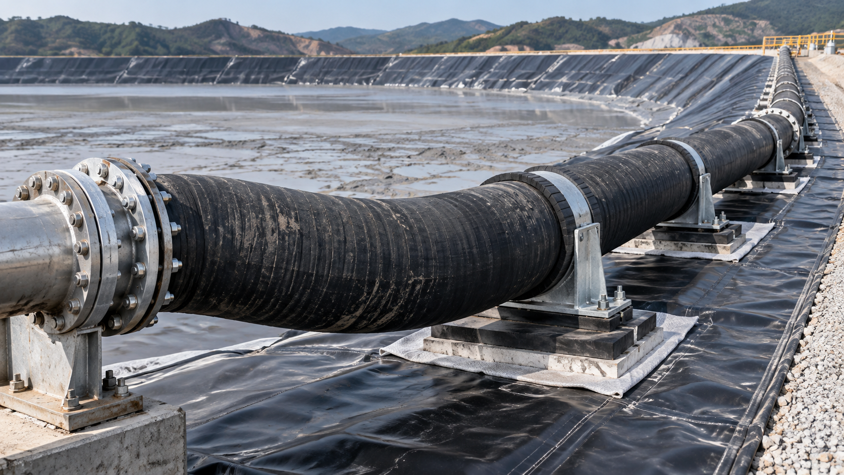
Mining Hoses Wearing Out Early? Check Slurry Velocity and Bend Layout
Are your mining hoses wearing out long before scheduled replacement? Repeated leaks and localized abrasion can signal more than a hose selection problem. Slurry velocity and bend layout may be accelerating damage: excessive velocity can intensify abrasive wear, while tight bends concentrate particle impact. Running too slowly creates a different risk—solids may settle and restrict the line.
Before ordering another replacement, establish where the damage starts, what the system was doing before failure, and whether the installed routing respects the hose’s minimum bend radius. A heavier wear liner may help in some applications, but it will not correct a kink, an internal restriction, or an operating cycle that repeatedly allows solids to accumulate.
Read the wear pattern before changing the hose
A failed hose is useful evidence. Mark its flow direction, installed orientation, bend position, and distance from the nearest pump, valve, reducer, or coupling before removal. Otherwise, a worn section on the workshop floor loses much of its diagnostic value.
Internal damage concentrated around the outside of a bend is consistent with particles striking the wall as the slurry changes direction. Wear near a coupling may indicate a bore mismatch, an exposed internal step, or disturbed flow. Damage along the bottom of a horizontal section can suggest solids traveling close to the invert, although the pattern alone does not prove inadequate velocity.
Keep external damage separate from internal abrasion. A cover rubbed through against steelwork needs a routing or support correction. Liner separation, cracking, and softening warrant checks for pressure cycling, temperature, chemical compatibility, or construction issues. Calling every failure “abrasion” can send maintenance teams toward the wrong remedy.
Do not investigate a suspected leak by approaching or touching a pressurized hose. Isolate, lock out, drain, and verify that pressure and stored energy have been released under the site procedure before inspection or disassembly.
Calculate velocity from the actual flow and bore
Average slurry velocity follows a straightforward relationship: v = Q/A. For a circular bore, A = πD²/4, where v is velocity in metres per second, Q is slurry volumetric flow in cubic metres per second, and D is internal diameter in metres.
The calculation is simple; choosing reliable inputs is harder. Use measured or otherwise validated slurry flow, not the pump’s nameplate capacity or a clean-water duty point. Confirm that the flowmeter is suitable for the slurry and operating conditions. Use the actual internal bore rather than assuming that every component has the nominal hose diameter.
Reducers, coupling inserts, and partly closed valves can create local restrictions even where the main hose velocity looks reasonable. Because cross-sectional area varies with diameter squared, a modest bore reduction can noticeably increase local velocity at the same flow rate.
Review more than the average production condition. Startup, flushing, pump-speed changes, changing solids concentration, and operation with different pump combinations can expose the hose to substantially different duties. A shift-average flow may conceal the short operating periods that cause the greatest damage.
There is no universal safe slurry velocity
The workable velocity range depends on particle size distribution, particle density and shape, solids concentration, carrier-fluid properties, pipe diameter, and inclination. Coarse settling slurry behaves differently from fine tailings with significant yield stress. A velocity copied from another installation is not a design basis.
Higher velocity can increase abrasive impact, but simply slowing the pump may allow a stationary bed to form. That bed reduces the available flow area and can lead to unstable operation or blockage. Establish the transport requirement using the project’s slurry design data, suitable engineering methods, and operating evidence; do not determine the minimum by deliberately running toward blockage.
Increasing hose diameter also needs a hydraulic check. It lowers average velocity at a fixed flow, but may compromise solids transport. Conversely, reducing diameter to keep solids moving can increase friction losses and local wear. The aim is a verified operating window, not the lowest possible velocity.
Inspect the installed bend—not just the drawing
A hose may leave the workshop with an acceptable layout and develop a damaging bend after installation. Pump movement, support settlement, hose weight, and repositioned equipment can change its shape. Check the route in its normal supported condition, including expected movement, without entering an unsafe operating area.
Compare the installed bend with the manufacturer’s minimum bend radius for the specific hose construction and service conditions. Confirm how that radius is defined. A hose that looks smoothly curved may still be too tight, particularly near an end fitting.
Minimum bend radius is a mechanical limit, not a guarantee of acceptable slurry wear. A bend can meet that limit and still concentrate particle impact. Where space permits, a broader, supported change of direction may reduce localized impact, but it also changes hose length, weight, and restraint requirements.
- Look for bending immediately behind a coupling, where stiffness changes and connection loads can become concentrated.
- Check for twist introduced during assembly. Use any manufacturer-provided alignment markings to help identify it.
- Inspect sags and low points that may retain solids during shutdown.
- Check supports for pinching, sharp contact edges, and unsupported spans that pull on fittings.
Adding spare length is not automatically an improvement. An oversized loop can create another low point or rub against nearby equipment. Where direction changes cannot be avoided, assess a revised route or a purpose-designed wear component rather than forcing a flexible hose into an unsuitable geometry.
Connect physical damage with operating history
Maintenance records become more useful when they connect hose condition to duty. Record operating hours alongside approximate slurry throughput, solids concentration, pump speed, and notable shutdowns. Hours alone can mislead when one replacement carries much more material than another.
Compare flow and pressure trends where instrumentation allows. Falling flow accompanied by rising upstream pressure may warrant investigation for restriction, although pump condition and control changes must also be considered. Repeated surges during startup or shutdown call for a transient-pressure review rather than an abrasion-only diagnosis.
Use consistent inspection locations and orientation marks to track deterioration. If wall-thickness monitoring is proposed, confirm that the method is suitable for the hose’s elastomer layers and reinforcement. Do not assume a technique used successfully on steel pipe will provide reliable remaining-liner measurements on a composite hose.
For a controlled improvement trial, change one major variable where practical. Correct the bend layout and compare performance under comparable duty before also changing liner material, bore, and pump settings. Otherwise, even a successful result leaves the cause uncertain.
Match the correction to the evidence
If wear is sharply localized at one bend, prioritize geometry, support, and connection alignment. If deterioration extends along the line, review velocity, particle characteristics, material compatibility, and total duty. If failures follow shutdowns, examine settling, flushing, and restart procedures.
Flushing deserves particular attention. The procedure must clear solids without exceeding hose pressure limits, creating unsafe discharge conditions, or leaving an unmanageable water volume downstream. Tailings facilities and lined containment systems may have specific limits on where flush water can go.
A thicker liner can offer additional wear allowance, but it may also change bore, weight, flexibility, and end construction. A different liner material may suit the particle impact or chemistry better, yet no material choice removes the need to verify working pressure, vacuum duty where applicable, temperature, and connection compatibility.
Avoid rotating an installed hose as an informal life-extension measure unless the manufacturer and site engineering team approve it. Redistribution of wear does not restore strength, and repositioning may introduce twist or load damaged reinforcement.
Protect the containment system around the hose
At tailings ponds and lined process-water facilities, hose maintenance also affects geosynthetic protection. Dragging couplings across a geomembrane, placing concentrated support loads on it, or allowing a leak jet to scour the surrounding surface can create a second maintenance problem beyond the failed hose.
Keep hose supports and movement paths consistent with the containment design. Protective geotextiles or load-spreading arrangements may be appropriate, but their suitability depends on loading, subgrade conditions, liner configuration, and project specifications. A loose piece of fabric beneath a heavy fitting is not automatically adequate protection.
Make the next replacement a documented correction
A useful supplier review starts with the failed hose’s wear map, actual flow range, slurry characteristics, pressure and temperature conditions, connection details, and a dimensioned routing sketch. Include the available bend envelope and support locations. These details are more valuable than requesting “a stronger mining hose.”
Shandong Hongyun Special Hose Co., Ltd. supplies industrial hoses alongside geomembranes and geotextiles, supporting overseas projects with customized configurations and export arrangements. For an integrated mining maintenance requirement, the practical task is to coordinate hose dimensions, geotechnical protection materials, packing, and required documentation—not to treat them as unrelated purchases. Certification and acceptance requirements should be confirmed against the particular project and destination.
Before installing another identical hose, resolve three questions: Is the slurry staying within a verified transport window? Is the installed route mechanically acceptable? Does the damage pattern support the proposed correction? If any answer remains unclear, retain the failed section and investigate it before repeating the same installation.
Related Posts
Contact Us
Leave A Message
If you are interested in our products and want to know more details, please leave a message here, we will reply you as soon as we can.